本文實例講述了Android開發自定義控件之折線圖實現方法。分享給大家供大家參考,具體如下:
折線圖是Android開發中經常會碰到的效果,但由於涉及自定義View的知識,對許多剛入門的小白來說會覺得很高深。其實不然,接下來我就以儘量通俗的語言來說明下圖折線圖效果的實現過程。

首先,選擇自定義控件的方式。
自定義控件的實現有四種方式:
1.繼承View,重寫onDraw、onMeasure等方法。
2.繼承已有的View(比如TextView)。
3.繼承ViewGroup實現自定義佈局。
4.繼承已有的ViewGroup(比如LinearLayout)。
由於我們不需要多個控件進行組合,也不需要在原有控件基礎上改造,故我們採用第1種方式即繼承View來實現。代碼如下,新建一個ChartView類繼承自View,並實現他的幾個構造方法,並重寫onDraw和onMeasure方法,因為我們要在onDraw方法裡面進行繪製工作,並且我希望這個控件的長寬是相等的,所以在onMeasure方法設置寬高相等。設置長寬相等的方式很簡單,我們不需要自己去測量實現,只需要調用父類的onMeasure方法,傳參數(寬高值)時將都傳入寬度(或者高度)即可。
public class ChartView extends View { public ChartView(Context context) { super(context); } public ChartView(Context context, @Nullable AttributeSet attrs) { super(context, attrs); } public ChartView(Context context, @Nullable AttributeSet attrs, int defStyleAttr) { super(context, attrs, defStyleAttr); } @Override protected void onMeasure(int widthMeasureSpec, int heightMeasureSpec) { super.onMeasure(widthMeasureSpec, widthMeasureSpec); } @Override protected void onDraw(Canvas canvas) { super.onDraw(canvas); } }
其次,繪製簡單圖形並顯示出來。
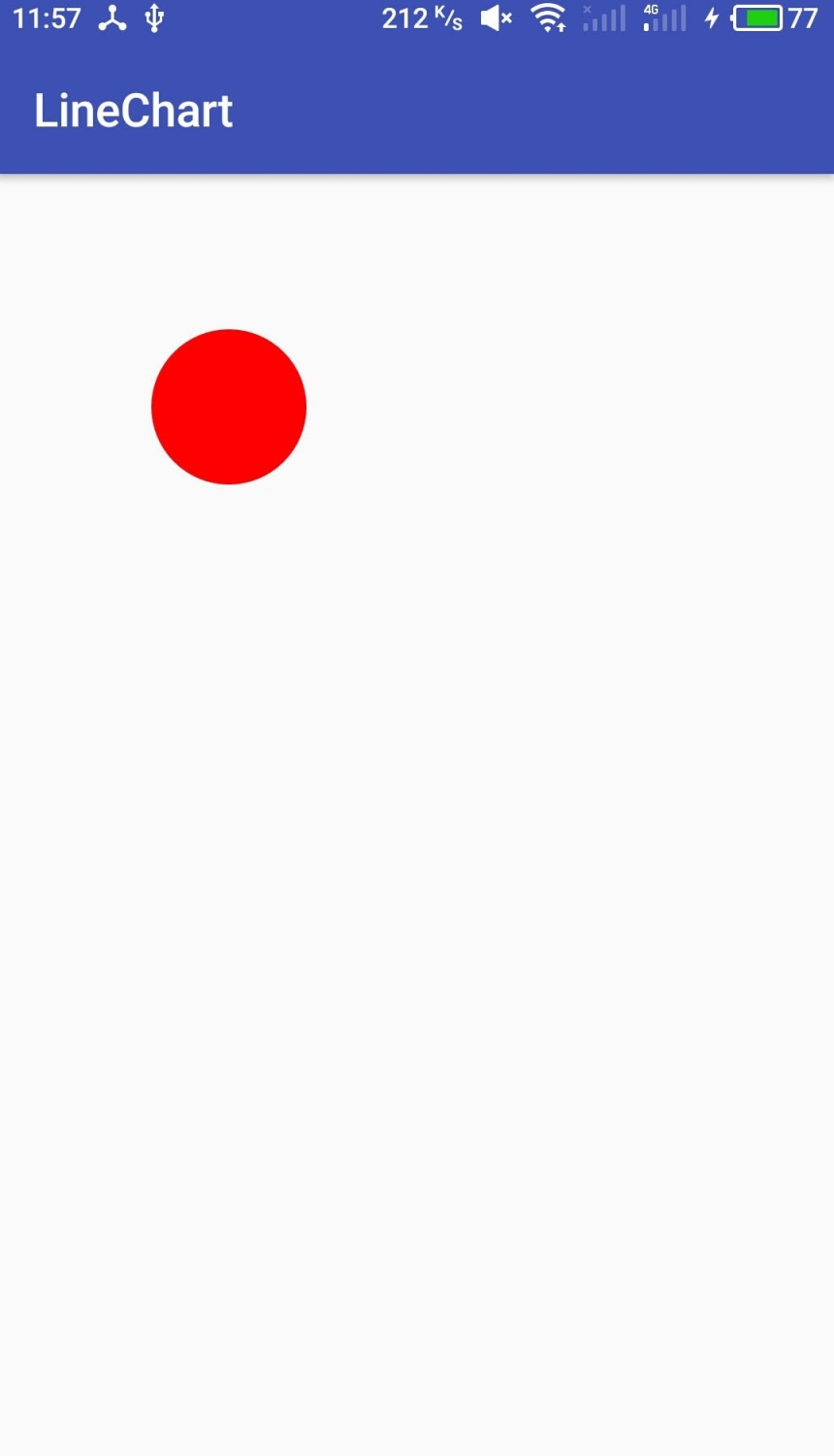
在進行繪製之前,我們要進行若干初始化工作,其中就包括畫筆的初始化。然後就可以進行繪製了,我們先繪製一個簡單的圓圈,然後將控件放到佈局文件中,運行看看效果。
ChartView代碼
public class ChartView extends View { // 畫筆 private Paint paint; /** * 構造函數 */ public ChartView(Context context) { super(context); initWork(); } /** * 構造函數 */ public ChartView(Context context, @Nullable AttributeSet attrs) { super(context, attrs); initWork(); } /** * 構造函數 */ public ChartView(Context context, @Nullable AttributeSet attrs, int defStyleAttr) { super(context, attrs, defStyleAttr); initWork(); } /** * 初始化工作 */ private void initWork() { initPaint(); } /** * 畫筆設置 */ private void initPaint() { paint = new Paint(Paint.ANTI_ALIAS_FLAG); // 畫筆樣式為填充 paint.setStyle(Paint.Style.FILL); // 顏色設為紅色 paint.setColor(Color.RED); // 寬度為3像素 paint.setStrokeWidth(3); } @Override protected void onMeasure(int widthMeasureSpec, int heightMeasureSpec) { super.onMeasure(widthMeasureSpec, widthMeasureSpec); } @Override protected void onDraw(Canvas canvas) { super.onDraw(canvas); // 畫圓 canvas.drawCircle(300,300,100,paint); } }
activity_main.xml
<android.support.constraint.ConstraintLayout xmlns:android="http://schemas.android.com/apk/res/android" android:layout_width="match_parent" android:layout_height="match_parent"
效果:
然後,繪製圖表。
到目前為止,已經實現了最簡單的一個自定義控件,雖然它什麼功能都沒有,只是簡單顯示一個紅色圓圈,但本質都是一樣的。接下來就開始圖表的繪製。
1.初始化一些需要使用的值。
// 刻度之間的距離 private int degreeSpace;
@Override protected void onDraw(Canvas canvas) { super.onDraw(canvas); // 控件上下左右邊界四至及控件的寬度(同時也是高度!) int left = getLeft(); int right = getRight(); int top = getTop(); int bottom = getBottom(); int w = getWidth(); // 圖表距離控件邊緣的距離 int graphPadding = w / 10; // 圖表上下左右四至 int graphLeft = left + graphPadding; int graphBottom = bottom - graphPadding; int graphRight = right - graphPadding; int graphTop = top + graphPadding; // 圖表寬度(也等同高度奧~) int graphW = graphRight - graphLeft; // 刻度之間的距離 degreeSpace = graphW / 8; }
2.灰色背景
// 背景 canvas.drawColor(Color.LTGRAY);
3.座標系
// 畫筆設置樣式為STROKE樣式,即只劃線不填充 paint.setStyle(Paint.Style.STROKE); // 座標系繪製 Path pivotPath = new Path(); //Y軸 pivotPath.moveTo(graphLeft, graphBottom); pivotPath.lineTo(graphLeft, graphTop); //Y軸箭頭 pivotPath.lineTo(graphLeft - 12, graphTop + 20); pivotPath.moveTo(graphLeft, graphTop); pivotPath.lineTo(graphLeft + 12, graphTop + 20); //X軸 pivotPath.moveTo(graphLeft, graphBottom); pivotPath.lineTo(graphRight, graphBottom); //X軸箭頭 pivotPath.lineTo(graphRight - 20, graphBottom + 12); pivotPath.moveTo(graphRight, graphBottom); pivotPath.lineTo(graphRight - 20, graphBottom - 12); canvas.drawPath(pivotPath, paint);
4.刻度虛線及數字
// Y軸刻度虛線 for (int i = 1; i < 8; i++) { Path yKeduPath = new Path(); // 線 paint.setColor(Color.WHITE); paint.setStrokeWidth(1); paint.setStyle(Paint.Style.STROKE); paint.setPathEffect(new DashPathEffect(new float[]{5,5},0)); yKeduPath.moveTo(graphLeft, graphBottom - i * degreeSpace); yKeduPath.lineTo(graphRight, graphBottom - i * degreeSpace); canvas.drawPath(yKeduPath, paint); // 數字 paint.setColor(Color.BLACK); paint.setStyle(Paint.Style.FILL); paint.setTextSize(25); paint.setPathEffect(null); canvas.drawText(i + "", graphPadding / 2, graphBottom - i * degreeSpace, paint); } // X軸刻度虛線 for (int i = 1; i < 8; i++) { Path xKeduPath = new Path(); // 線 paint.setColor(Color.WHITE); paint.setStyle(Paint.Style.STROKE); paint.setStrokeWidth(1); paint.setPathEffect(new DashPathEffect(new float[]{5,5},0)); xKeduPath.moveTo(graphLeft + i * degreeSpace, graphBottom); xKeduPath.lineTo(graphLeft + i * degreeSpace, graphTop); canvas.drawPath(xKeduPath, paint); // 數字 paint.setColor(Color.BLACK); paint.setStyle(Paint.Style.FILL); paint.setTextSize(25); paint.setPathEffect(null); canvas.drawText(i + "", graphLeft + i * degreeSpace, graphBottom + graphPadding / 2, paint); }
5.折線
在繪製折線之前,我們先要初始化幾個參數。
// 模擬數據 private float[] data = {3.2f, 4.3f, 2.5f, 3.2f, 3.8f, 7.1f, 1.3f, 5.6f}; // 當前顯示的數據數量 private int showNum=1;
// 折線 Path linePath = new Path(); for (int i = 0; i < showNum; i++) { int toPointX = graphLeft + i * degreeSpace; int toPointY = graphBottom - ((int) (data[i] * degreeSpace)); paint.setColor(Color.YELLOW); paint.setStyle(Paint.Style.STROKE); if (i==0){ linePath.moveTo(toPointX,toPointY); }else { linePath.lineTo(toPointX, toPointY); } // 節點圓圈 canvas.drawCircle(toPointX, toPointY,10,paint); paint.setColor(Color.WHITE); paint.setStyle(Paint.Style.FILL); canvas.drawCircle(toPointX,toPointY,7,paint); } paint.setColor(Color.YELLOW); paint.setStyle(Paint.Style.STROKE); paint.setStrokeWidth(3); canvas.drawPath(linePath, paint);
6.讓圖表動起來
為了實現數據依次顯現的動畫,我們開啟一個線程是當前顯示的數據數量即showNum變量不斷加一,並間隔時間0.5秒。然後postInvalidate()重繪即可。
private void initWork() { initPaint(); // 開啟線程,沒隔0.5秒showNum加一 new Thread(new Runnable() { @Override public void run() { while (true){ if (showNum<data.length){ showNum++; }else { showNum=1; } // 重繪 postInvalidate(); // 休眠0.5秒 try { Thread.sleep(500); } catch (InterruptedException e) { e.printStackTrace(); } } } }).start(); }好了,運行一下,便會實現上面的效果了。如果你覺得效果不夠炫酷或者功能太少,那就自己完善吧~~
由於自定義控件是Android進階路上必然要碰到的知識,所以希望大家重視。其實自定義控件說難也難說簡單也簡單。實現一些普通的效果還是很方便的,像這次舉的例子,但如果要實現各種炫酷效果並且要完善各種功能的話,就需要各種知識的配合了,包括數學、物理、繪圖等知識。所以還是需要平時不斷積累的,看到別人的控件很棒的時候自己可以試著去實現一下,對自己的知識庫不斷進行補充,自然會嫻熟的運用。本人也是菜鳥一枚,望共勉!!
[madbeef ] Android開發自定義控件之折線圖實現方法詳解已經有670次圍觀
